Six processes. Each one drawn, dimensioned and explained.
How each operation actually works, what it's good at, the numbers we plan around, and the small design choices that make a part cheaper and more accurate to make.
Fibre laser cutting
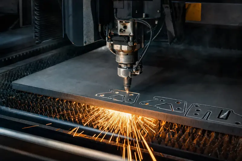
A focused beam melts a narrow kerf while assist gas blows the melt clear. Nitrogen gives a clean, oxide-free edge on stainless and aluminium; oxygen cuts thicker mild steel faster. Parts are nested across the sheet and held with micro-joints so they don't tip into the slats.
| Material | Max thickness | Assist gas | Edge |
|---|---|---|---|
| Mild steel | 20 mm | O₂ (N₂ to 6 mm) | Light oxide on O₂ cuts |
| Stainless 304 / 316L | 12 mm | N₂ | Bright, weld-ready |
| Aluminium 5052 / 5083 | 10 mm | N₂ | Slight dross above 6 mm |
Design for laser
- Holes no smaller than the material thickness. Smaller ones can be cut, then reamed or drilled.
- Keep tabs and slots at least 1× thickness wide so they don't overheat.
- Send DXF at 1:1 in millimetres, with bend lines on their own layer.
CNC milling
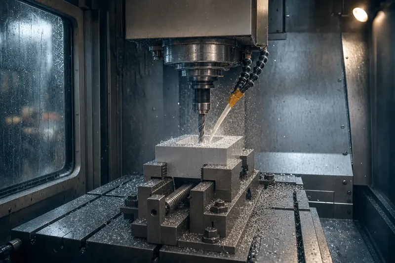
A rotating cutter removes material while the table moves the work beneath it. We use it for flat datums, H7 bores, pockets, tapped holes and, often, finishing a welded assembly so the critical features are true to each other after the heat has done its worst.
| Feature | Routine | With care | Checked with |
|---|---|---|---|
| Linear position | ±0.05 mm | ±0.02 mm | Height gauge, CMM by subcontract |
| Bore | H8 | H7 | Bore gauge, go/no-go plug |
| Flatness | 0.05 mm | 0.02 mm | Surface plate and indicator |
| Surface finish | Ra 3.2 | Ra 1.6 | Comparator plates |
Design for milling
- Give internal corners a radius: a Ø10 cutter leaves R5 whether the drawing says so or not.
- Tolerance only what matters. ISO 2768-m everywhere else keeps cycle times honest.
- Mark which faces are datums; we'll fixture from them.
CNC turning
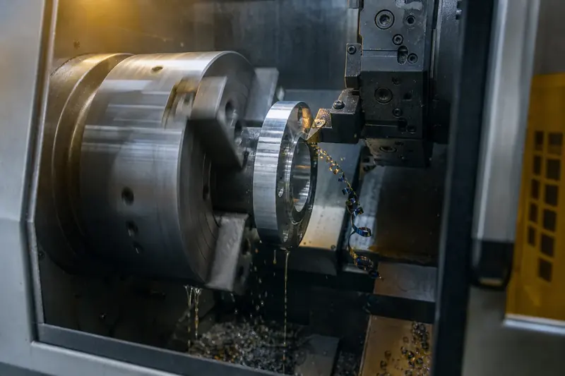
The work spins; the tool moves in X and Z. Turning is the fastest way to make round parts concentric (bushes, spacers, pins and flanges), and bar feeding means repeat batches run with very little handling.
| Feature | Routine | With care | Checked with |
|---|---|---|---|
| Diameter | ±0.02 mm | h6 / H7 | Micrometer, bore gauge |
| Concentricity | 0.05 mm | 0.02 mm | V-block and indicator |
| Length | ±0.05 mm | ±0.02 mm | Height gauge |
| Surface finish | Ra 1.6 | Ra 0.8 | Comparator plates |
Design for turning
- Machine OD and bore in one setting when they must be concentric, say so on the drawing.
- Undercuts and thread reliefs save a lot of fuss at shoulders.
- Standard bar sizes (Ø25, 32, 40, 50, 65…) cut material cost.
Press brake folding
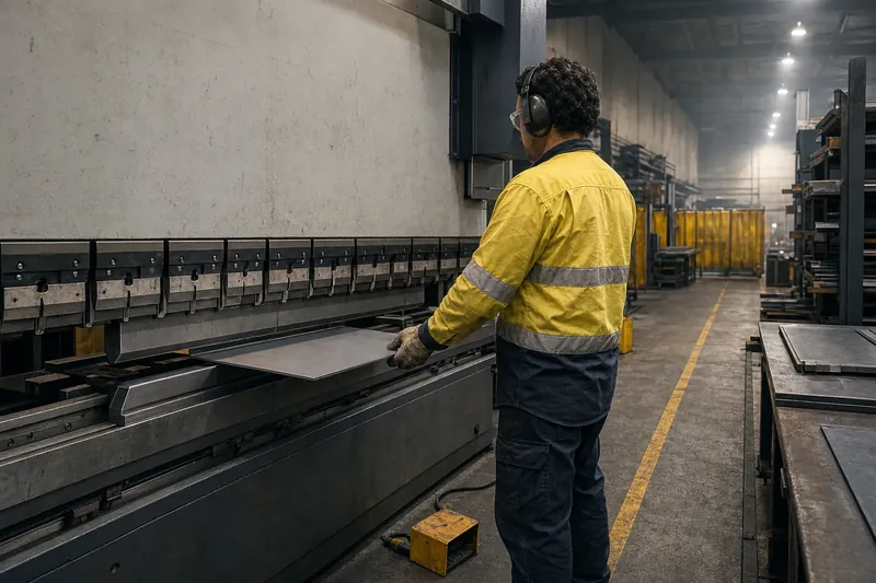
A punch drives the sheet into a V-die. The die opening, the material and its thickness set the inside radius and the minimum flange, which is why we ask about bend radius when a drawing leaves it blank, rather than assuming.
| Thickness | Die V | Inside radius ≈ | Min. flange |
|---|---|---|---|
| 1.6 mm | 12 mm | 2.0 mm | 8 mm |
| 2.0 mm (.080″) | 16 mm | 2.6 mm | 10 mm |
| 3.0 mm | 24 mm | 4.0 mm | 15 mm |
| 6.0 mm | 50 mm | 8.0 mm | 30 mm |
Design for folding
- Keep holes at least 2× thickness plus the radius away from a bend line, or they'll stretch.
- Use one inside radius across the part so it folds in one tool set-up.
- Dimension flanges to the outside: that's what we measure.
MIG and TIG welding
MIG is quick and strong for carbon-steel frames and brackets. TIG is slower and more controlled, and our choice for stainless, aluminium and anything visible. Either way, the weld symbol on the drawing decides the size and the sequence decides the distortion.
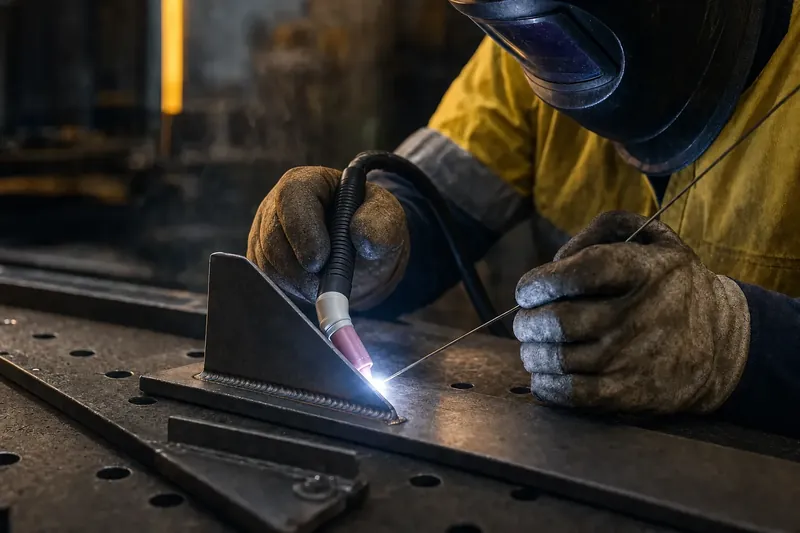
| Process | Materials | Planning rate | Typical use |
|---|---|---|---|
| Pulsed MIG | Carbon steel, some stainless | ≈ 250 mm/min | Frames, brackets, structural fillets |
| TIG (DC) | Stainless, carbon steel | ≈ 120 mm/min | Food-grade, visible and thin work |
| TIG (AC) | Aluminium | ≈ 100 mm/min | Covers, tanks, frames |
Design for welding
- Put a weld symbol on every joint. "Weld all round" is a price-on-application note.
- If a bore or face must be true, machine it after welding and say so.
- Leave torch access: about 45° and 30 mm clear for TIG.
Finishing
Surface preparation does most of the work. We blast to a profile the coating can grip, pretreat, then send parts to trusted coaters and galvanisers. Stainless is pickled and passivated to restore the chromium oxide layer after welding.
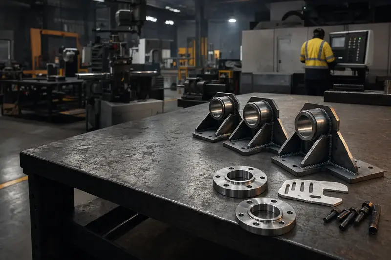
| Finish | Where | Suits | Notes |
|---|---|---|---|
| Bead / grit blast | In-house | All metals | Uniform satin, or profile for coating |
| Pickle & passivate | Subcontract | Stainless | Removes heat tint after welding |
| Powder coat | Subcontract | Steel, aluminium | Specify RAL colour and texture |
| Hot-dip galvanise | Subcontract | Carbon steel | Needs vent and drain holes; we'll mark them |
| Black oxide | Subcontract | Steel, 4140 | Minimal dimensional change, light protection |
Design for finishing
- Name the finish on the drawing or PO. "Refer purchase order" with no PO is a question we'll send back.
- Mask threads and H7 bores, or allow for coating build-up.
- Hollow sections being galvanised need vent holes; we'll propose positions.
Not sure which route?
Send the drawing. We'll propose a process route, explain the trade-offs, and price it from our rate card.
Request a quote